

THE BASIC PRINCIPLE
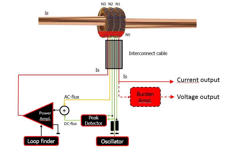
The primary current lp generates a magnetic flux that will be counteracted by the current ls in the secondary
winding INs) of the measuring head. Any remaining flux is sensed by three toroidal · wound ring cores located
within the secondary winding volume.
Two of them (N1, N2) are used l0 sense the DC port of the remaining flux. N3 senses the AC part. An oscillator
drives the Iwo DC flux-sensing cores into saturation in opposite directions. The resulting current peaks are
equal in both directions if the remaining DC flux is zero. If not zero, their difference is proportional
lo the residual DC flux, The Zero-flux CT hos a double peak detector to find the DC flux. After adding the AC
component (N3), a control loop is set up l0 generate the secondary current that makes the flux zero. A power
amplifier provides this current ls to the secondary winding Ns. The secondary current, which is a scaled image
(1/Ns) of the primary current, is fed to the burden resistor to convert the signal into a voltage. The signal
across the burden is amplified to make the, signal available for further use. The unique design of the
Zero-flux CT system provides high accuracy and stability without the need for temperature control devices.
Above several kHz, the power amplifier no longer has active control over its output current, but merely forms
a short circuit. The Zero-flux CT still performs as 0 wideband current measuring device, but now with the
measuring head as a passive current transformer. The external bandwidth is only limited by, the stray reactance
and capacitance in the head and interconnecting cable.
In case os a Zero-flux CT with current output, the secondary current is the output, omitting in that case the
burden resistor and precision amplifier.
If the core saturated due to primary overload, the zero flux condition is lost, and a search cycle is started
automatically, This means the secondary current is swept between the minus and plus current limits in o slow
triangle until zero flux is detected, and normal tracking continues. The same happens when the auxiliary power
is switched-on with primary current present.
THE BURDEN RESISTOR
In view of required measurement precision a four-wire resistor is the best. The power dissipation is kept very
low, because the voltage drop across the resistor (usually 0.5V at rated current) is low. The thermal stability of the
burden resistor, under normal load conditions, is ensured even over the long lime.
THE PRECISION AMPLIFIER
The precision amplifier is a very stable differential amplifier, which delivers a highly accurate output
voltage, proportional with the secondary current through the burden resistor. To ensure that the gain factor remains
constant, the temperature coefficients of the gain-selling resistors ore matched m tracking). The offset error
is minimized by careful selection of the operational amplifier and retuned during adjustment. The gain,
usually 20tc, is factory adjusted in order l0 compensate for tolerances in burden and gain · setting resistors. The
output usually delivers 10V at the rated current and may
be loaded by up Io 5mA.
CTs and DCCTs
Convectional AC measurement Current Transformers (CTs) lack the capability to measure currents at low frequencies
(for example 5Hz, as found in frequency inverter drives). DC current will not be transformed at all, as it saturates
the transformer. AC with some DC might saturate a conventional transformer, or at least strongly distort the current shape.
The PM Special measuring Systems Direct-Current Current Transformer (DCCT), based on the Zero-flux principle, is able
to measure current in a wide bandwidth (DC to 500kHz) with a very high accuracy. PM Special Measuring DCCTs eliminate
measuring errors which may arise with conventional AC transformers.
